Connected Component Labelling (CCL) is one of available technique used to classify object or region on digital imaging research field (Abubaker dkk., 2007). This technique apply connectivity theory between pixels exist on image. The pixels on a specific region is connected while all of them have same value and restricted by background. Every label resulted after CCL process is unique and separated minimun by on background space (Kalentev et. al, 2011).

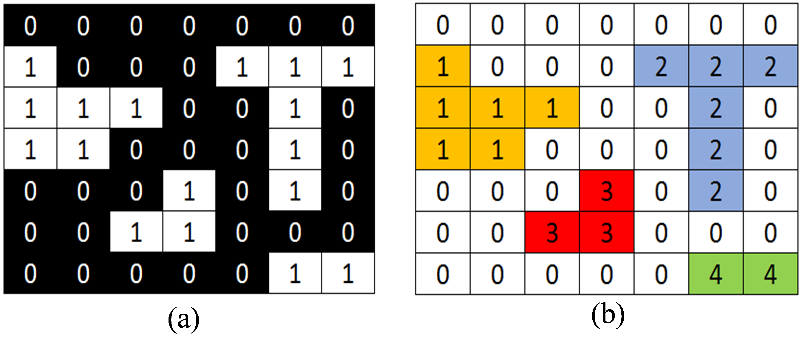
Figure 1 (a) Simple binary image for labelling input and (b) labelling result using CCL method
CCL method is able to perform labelling every connected region using unique label (using label entry). Therefore, by keepng information about total used label on it, the number of object existed on binary image will be known. Another information can be determined such as object area, object heigh, and object center.
To perform object labelling using CCL method, one can be done using these steps below:
- Check the first pixel value on input image ( first column and first row)
- If pixel value is 0 (background), skip and move to next column of pixel but still in same row.
- If pixel value is 1 , check its neighbour value and use terms below :
- If its nearest neighbour still not labelled yet, label this pixel using label 1.
- If only one of nearest neighbour was labelled, give same label to this pixel using neihbour's abel.
- However, if there were 2 or more labels exist on neighbours, use the smallest label to label this pixel.
- After labelling each pixel and skipping the background, don't forget to update the label.
- Perform this process on entire columns and rows.
Labelling result using CCL method depends on connectivity configuration used in neighbour's label checking. There are 2 connectivity cofiguration can be used in CCL method as follows:

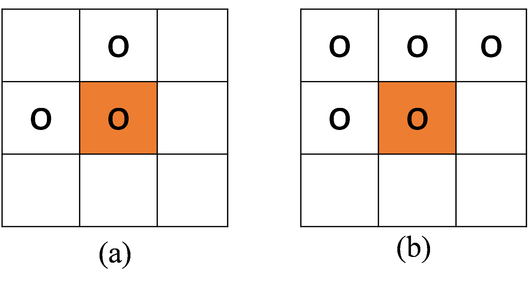
Figure 2 Number of connectivity configuration, (a) 4 conectivity, and (b) 8 conectivity
By using 4-conectivity, pixel value checking only performed on 2 nearest neighbours (west and north neighbour). In the other hand, 8 connectivity uses 4 point checking (Figure 2).
Advantages and disadvantages caused by number of connectivity selection is determined by this method application. As an example, 4 connectivity configuration could not detect slanted object, but it can be performed faster than 8 connectivity because it only check for 2 neighbours. However, 8 connectivity is able to detect more complex objects even though need longer time to perform this method.
Advantages and disadvantages caused by number of connectivity selection is determined by this method application. As an example, 4 connectivity configuration could not detect slanted object, but it can be performed faster than 8 connectivity because it only check for 2 neighbours. However, 8 connectivity is able to detect more complex objects even though need longer time to perform this method.

On MATLAB, performing CCL method can be done using these functions
-bwconncomp
-bwareaopen

